CCC Architecture
Programs in Architectural Studies at the City Colleges of Chicago
Introduction to 2D AutoCAD
Generally, there are two types of graphic software.: raster and vector. Raster software uses pixels, small squares of color to define an image. Photoshop is an example of a raster software.
Vector software is coordinate based. It works with points to define lines, circles, polygons and other geometric entities. AutoCAD is a vector software.
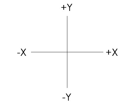
For a vector software the positions of objects are located relative to an x-axis and a y-axis. When you work in 3D, there is also a z-axis, but to start off we'll be working in 2D.
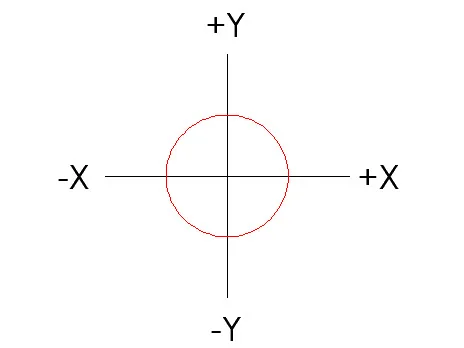
At the intersection of the two axes is coordinate point 0,0. The first 0 represents the position on the x-axis. The second 0 represents the position on the y-axis. The red circle has it center at coordinate point 0,0.
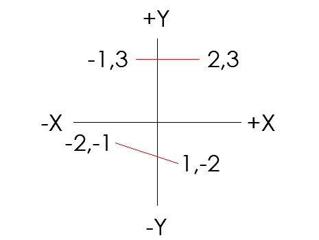
Two red lines and the coordinate points that identify their endpoints are shown below.
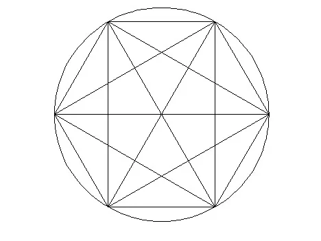
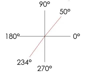
Angled lines are drawn using the following degrees. By default operations work in a counter-clockwise direction.
There are numerous components in the AutoCAD workspace. It will be helpful to memorize the terms below and their locations. The terms will be referenced in the course tutorials.
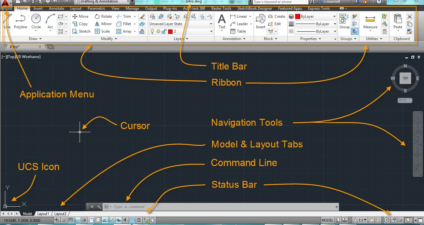
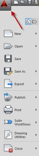
Application Menu (Big A in upper left corner): Use this to print and perform file management functions.
Title Bar: This is where you will find the file name for the current file. The drawing file in the image below is named Drawing2.dwg. Most of the work you will do is in a drawing file. ".dwg" is the file extension for this type of file.

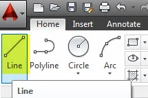
Ribbon: On the ribbon you will find icons for many of the operations. The image below shows a small portion of the Home ribbon. The Line tool has been selected. Click on the tabs next to Home to open the different ribbons.
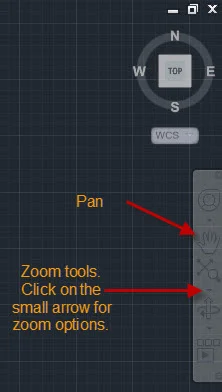
Navigation Tools: These tools can be used to move around the drawing and zoom into areas. For two-dimensional drawing the Pan and Zoom tools are the most useful. You can also hold down the roller on your mouse and drag the cursor across the screen to pan. You can roll the roller on your mouse to zoom in and out.
Model & Layout Tabs: Click on these tabs to go from model space where you do most of your drawing to the sheets where you print.
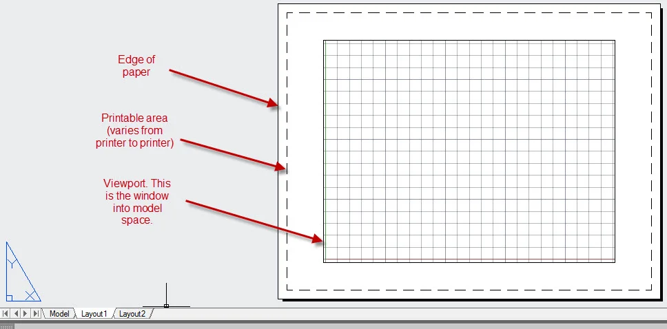
Most of the drawing that you do is in model space. By default model space has a black background. When you draw in model space, you draw to full scale. Unlike drawing on paper there is no shrinking of the object that you are drawing. If something is 200 feet long, then it is drawn 200 feet long.

Layout views (also known as paper space) are where you set up your sheets and where you print. Typically, very little information is drawn in paper space.
Command Line: You can type in commands here instead of selecting them from the ribbon or selecting them from drop down menus. Sometimes this is faster. You will also see options or requests for additional information there.
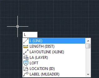
It is possible to initiate many operations in more than one way. You could select the Line tool from the ribbon. The command line is another way. You simply begin typing a command. In the image below the letter "L" was entered. A list of commands that start with L appear. If you want to make a line, you can continue typing in the word or select it from the list.
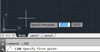
When you enter a command, you will be asked for additional information. In the image below, the first point of a line has been requested. X and Y coordinates could be added or points could be selected with the cursor.
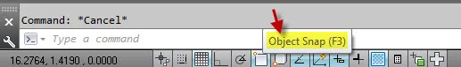
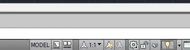
Status Bar: This bar lets you know what some of the current settings are. Keep in mind that if you rest your cursor on top of the icons along the status bar and elsewhere on the screen, you will see the name of the icon. Both the left and right ends of the status bar are shown below.
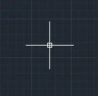
Cursor: This icon/symbol tells you where your are within the workspace. It moves as you move your mouse.
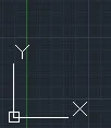
UCS Icon: UCS stands for User Coordinate System. This icon tells you where the coordinate point 0,0 is. If coordinate point is off the page, the UCS icon will appear in the lower left corner.
For a more detailed explanation of some of the characteristics of the AutoCAD work environment, you might find the videos at the following link useful. 2D Drafting Basics
.
.