CCC Architecture
Programs in Architectural Studies at the City Colleges of Chicago
Analyzing Architecture through Diagrams
A building or space can be analyzed on many levels. typically, the analysis is represented through diagrams. The content on this page explains and illustrates some of the means of analyzing architecture. They are divided into categories.

A. Spatial Zones:
A.1. Circulation Space (Ambulatory) vs. Programmed Space (Dwelling)
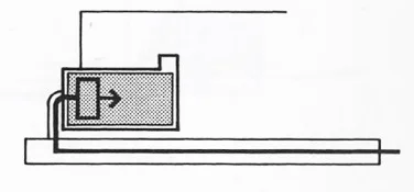
A.2. Servant vs. Served Space
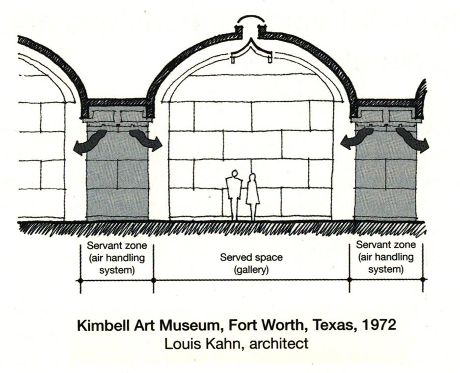
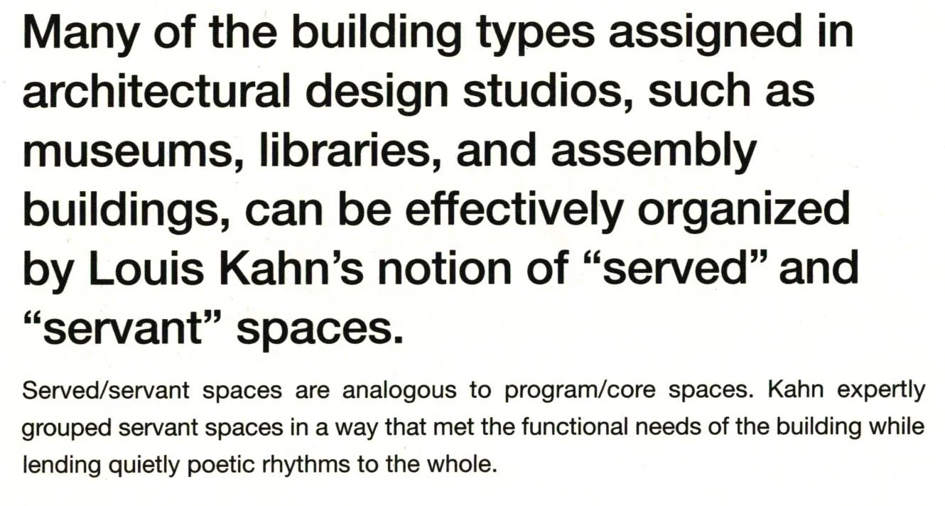
from 101 Things I Learned in Architecture School by Matthew Frederick, pp. 73-4.
A.3. Personal, social and public

B. Systems:
B.1. Circulation
In the plan below a bold line and arrow illustrate the entry pathway.
Chapel on Mt. Rokko by Tadao Ando from Precedents in Architecture
The image below shows circulation paths within an existing building.
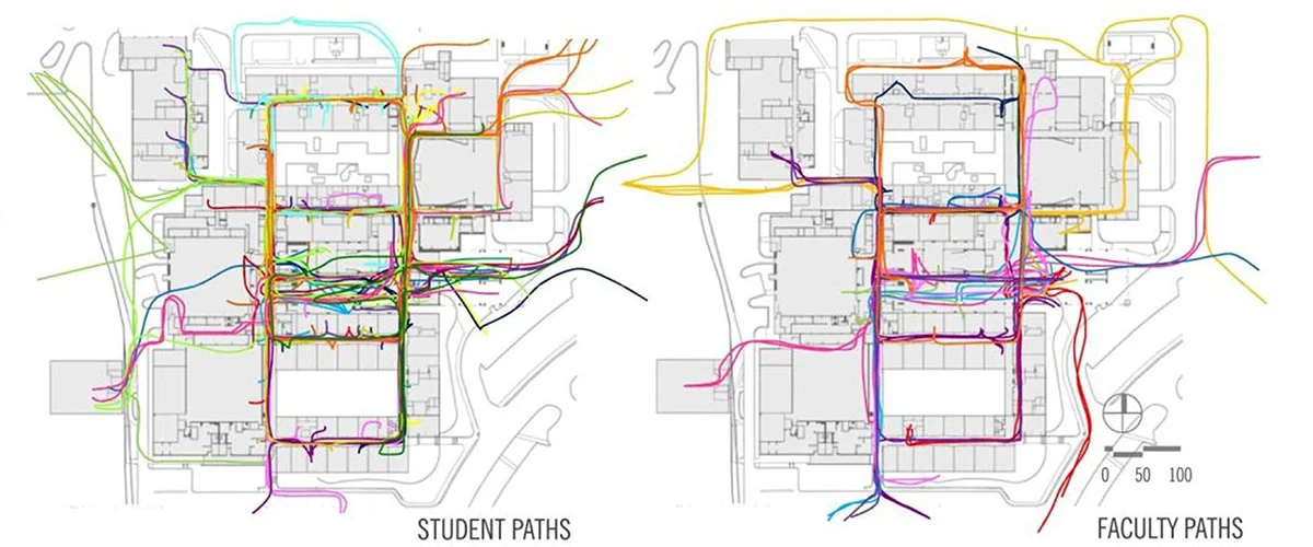
http://www.gouldevans.com/portfolio/manhattan-high-school
The diagram below illustrates the circulation path in 3D. The lineweights of the building are ghosted and the circulation path is bolded to make the diagram more clear.

http://openbuildings.com/buildings/musee-de-louvain-la-neuve-profile-4705#!buildings-media/3
The diagram below show paths on different levels of a building.

https://67.media.tumblr.com/2c770a6327cf28df36be9e238ee77bad/tumblr_inline_mhmp3jjOSJ1re5qp1.jpg
The diagram below shows accessible paths through a park.

https://hecker.wordpress.com/tag/merriweatherpostpavilion/
B.2. Structural
In the plan diagrams below columns are represented with dots and bearing walls are represented with lines. Hidden lines indicates a beam above.
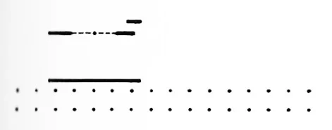
Structural Diagram, Chapel on Mt. Rokko by Tadao Ando from Precedents in Architecture
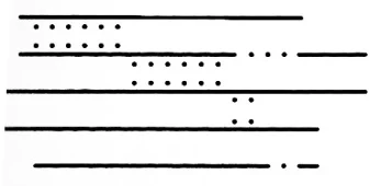
Structural Diagram, LiangzhuCultureMuseum by David Chipperfield from Precedents in Architecture
B.3. Ordering System: Grid
Often a grid is used to arrange and order space. With this type of diagram the grid is overlaid upon the plan.
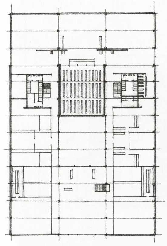
Floor Plan with Structural Grid Expressed. IIT Library by Mies Van der Rohe from Architecture: Form Space and Order
B.4. Proportioning Systems
B.5. Geometry
Geometry diagrams illustrate the relationship of the underlying geometric order. Unlike a floor plan (as shown below), a geometric diagram does not show wall thicknesses nor does it show minor details. An example of a geometric diagram is below the plan.
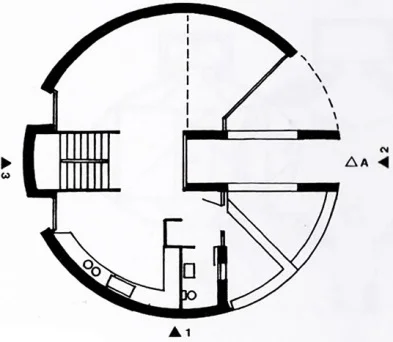
Plan, Bianda Residence by Mario Botta, from Precedents in Architecture
Plan, Bianda Residence by Mario Botta, from Precedents in Architecture

C. Formal and Spatial Relationships:
C.1. Alignment
C.2. Axiality
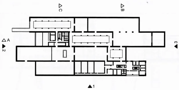
Axiality has to do with the path where openings line up along a straight line. It may seem to be the same as symmetry, but an axis does not need to run through the middle of spaces. The horizontal axis shown above, for example, is not in the center of the rooms.
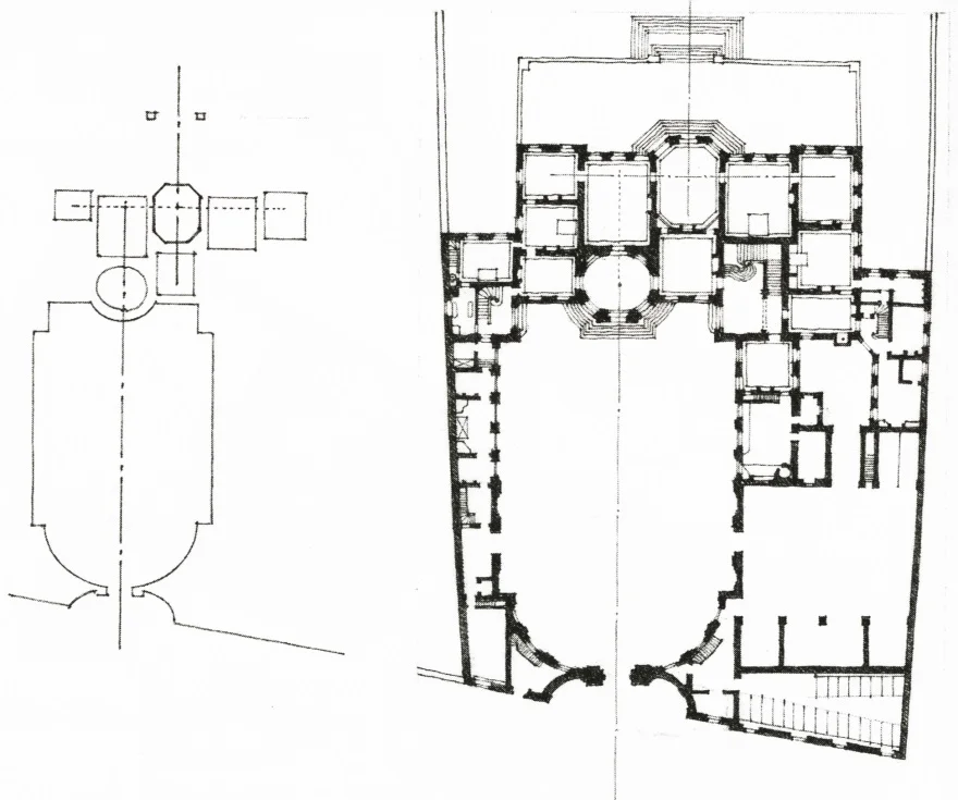
Axis Diagram (left), Plan (right), Hotel de Matignon by JCourtonne
C.3. Boundary
The diagram below shows the Renaissance walls that surround the town of Urbino, Italy. By not showing all of the buildings inside we clearly see the boundary. Boundaries can be both man-made and natural elements.

From Visual Notes for Architects and Designers by Crowe and Laseau, p. 42.
C.4. Hierarchy
C.5. Position
C.6. Scale
C.7. Solid to void/Figure-Ground
The relationship of solid to void is the relationship of masses to open spaces. Solid void diagrams can be shown as three-dimensional drawings or as physical models as shown below.
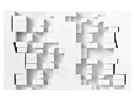
http://www.festivalarchitettura.it/Upload/Articoli/x16Fvj2VUp_846.jpg
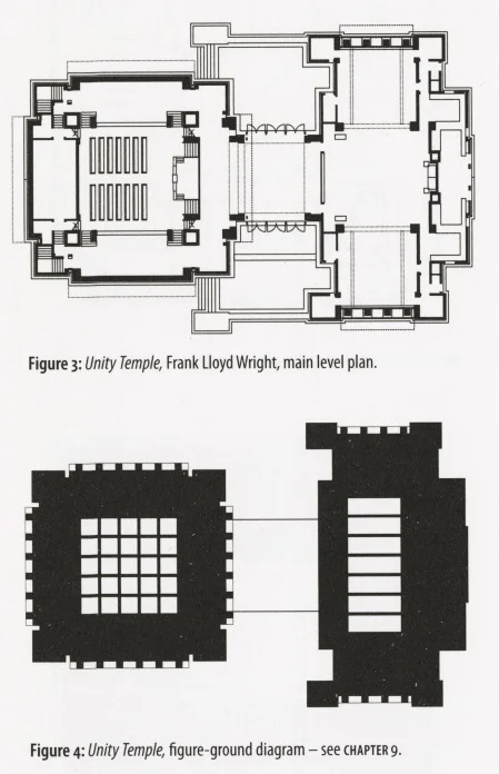
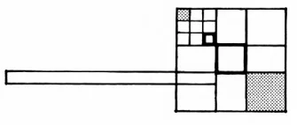
The concept is illustrated as a figure-ground diagram in two-dimensional representations. A floor plan and figure-ground diagram is shown below. The dark areas represent areas of the plan that are more enclosed. The area between the two dark areas is spatially more open. The light squares and rectangles inside the dark areas represent skylights.
In the plan below the buildings of Urbino, Italy are filled with tone, and the streets and public spaces are left white. Important places are noted as well.

From Visual Notes for Architects and Designers by Crowe and Laseau, p. 43.
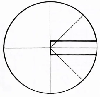
C.8. Symmetry
In the plan diagram below lines have been drawn that indicate mirror lines. The plan is identical if folded along those lines. This plan is bilaterally symmetrical along the compass axes as well as along the diagonals. It is also radially symmetrical about the center. The diagram for this could be simplified with single lines indicating the shapes of each room.
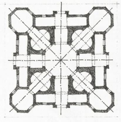
Symmetry Diagram, Church by AntonioFilarete
The following is from Clark, Roger H., and Michael Pause. Precedents in Architecture. New York: Van Nostrand Reinhold, 1985. pages, 251-2.

Site Plan. Kingo Houses by Jorn Utzon. http://andrea-in-denmark.blogspot.com/2009/10/more-jrn-utzon-kingo-houses.html

D. Configuration/Parti/Concept:
The overall configuration or organization of the project is sometimes referred to as its parti or a concept. Some designers refer to the parti or concept as, "the big idea."
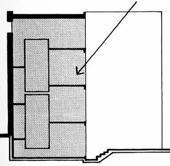
A plan and parti diagram are shown below. The parti is a simplified version of the plan, and it describes the overall configuration or organization of the building. The diagram shows a series of detached bars with toned areas representing courtyards. A verbal description of the parti could be, "Shifted bars punctuated by open courtyards."
Plan, LiangzhuCultureMuseum by David Chipperfield from Precedents in Architecture

Parti Diagram, LiangzhuCultureMuseum by David Chipperfield from Precedents in Architecture
Generally, we assoicate the term 'parti' with a plan diagram, but a concept can also be shown as a section diagram. Below is the section/elevation followed by the sectional concept diagram. The house sits on a hill. An bridge connects the hill to the entry. This house also has a plan parti which is shown below the section concept diagram.
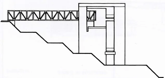
Elevation, Bianchi Residence by Mario Botta, from Precedents in Architecture
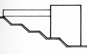
Section Concept Diagram, Bianchi Residence by Mario Botta, from Precedents in Architecture
Parti, Bianchi Residence by Mario Botta from Precedents in Architecture

E. Perceptual Conditions
E.1. Enclosure and volume definition
E.2. Light interaction
The diagram below illustrates how light enters some of Louis Kahn's buildings.

Tone indicates interior space. An arrow represents the direction and angle of the sun through glass.
Section, Bianda Residence by Mario Botta from Precedents in Architecture
E.3. Sequence
E.4. Surface characteristics (color, texture, etc.)
E.5. View framing

F. Tectonics
Tectonics are basically, the means and manner of assembly of building components.
Examples: Assembly Drawings

G. Details
Details can be more tectonic like the one below and to the right. They can also be used to study the proportions or arrangement of a fragment.
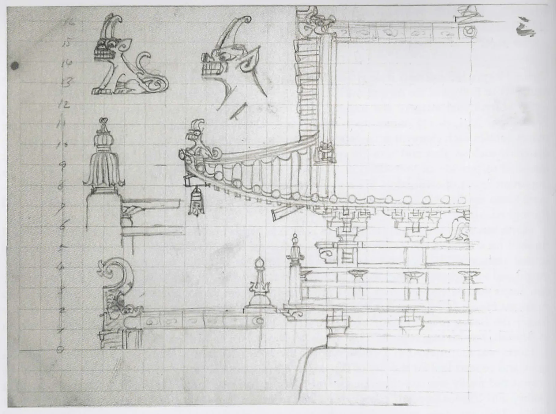
Ito, Chuta. Sketch of gate of Shrine Shinobazu Bentendo Tenryumon, 1914. Graphite on grid paper. The University of Tokyo Tokyo. New York. Architects’ Drawings: A Selection of Sketches by World Famous Architects Through History. Amsterdam: Elsevier/Architectural, 2005. 132. Print.

References:
Clark, Roger H., and Michael Pause. Precedents in Architecture: Analytic Diagrams, Formative Ideas, and Partis. Hoboken, NJ: John Wiley & Sons, 2012.
Crowe, Norman, and Paul Laseau. Visual Notes for Architects and Designers. New York: Van Nostrand Reinhold, 1984.
.
..