CCC Architecture
Programs in Architectural Studies at the City Colleges of Chicago
A Small House
In this exercise you will be planning a small house. The house will be a single story structure and will have flat or simple geometric roofs. A grid will be used to establish locations for walls and other building components. The drawings will be drawn at their full size, but scaled in the viewport to a smaller size.
Objectives/Outcomes and Assessment Criteria
Students will acquire and demonstrate: 1.) technical competency in working with basic drafting tools, scaled viewports, and block creation and insertion, 2.) sense of craft through precision and care in the presentation of the work, 3.) design aptitude in the ability to solve an organization problem and explore possible solutions, 4.) judgment in the composition of objects within a field. 5.) consideration of limitations and constraints in the problem solving process.
Part 1
SH.1.1. Make a new file using the acad template. Name the file with your first name followed by your last name followed by SmallHouse.
SH.1.2. For architectural drawings there are standards for naming layers. Not all firms use these standards, but most do or use some variation. This makes it easier for teams to work together on the same project and for drawings to be shared between disciplines. The architect may, for example, share his/her drawings with a structural engineer. Using a standard set of layer names, it is easier for the structural engineering to work in the drawing. National CAD Standards for layer naming can be found at this link.
Using the National CAD Standards create a set of layers for the items described below. Your layers should use the Discipline Designator, Level 1, the Major Group and, in some cases, the Minor Group. Use all caps for your layer names.
Layer name, A-DOOR; color 6 so it is light when it prints
Layer name, A-FURN; color 8 (Furniture blocks can be inserted on this layer)
Layer name, A-OBJT-ABOV; color 6, linetype Hidden2 (This layer is for objects in the plan that are above the cut plane).
Layer name, A-WALL-FULL; color 4 so it is a heavy line when it prints (This layer is used for full-height walls.)
Layer name, A-WALL-PART; color 6 (This layer is used for low walls that are below the plan cut line.)
Layer name, A-WALL-FILL; color 253
Layer name, A-WIND-FRAM; color 5 (For window frames)
Layer name, A-WIND-GLAS; color 7 (For window glass)
Layer name, A-WIND-SILL; color 8 (For window sills)
Layer name, A-APPL; color 8 (For appliances)
Layer name, I-FURN; color 8 (That's a capital letter I, not number 1. This discipline designator is for Interiors. Furniture blocks can be inserted on this layer)
Layer name, I-MLWK; color 6 (For millwork and cabinetry)
Layer name, P-FIXT; color 6 (For plumbing fixtures)
Layer name, X-CNST; color, any color (Click on the printer icon so the layer does not print. Technically, the X designation is for items that are not in contract, but I also use the layer for items that I don't want to appear.)
Layer name, X-GRID; any color but choose a dark color (click on the printer icon so the layer does not print)
SH.1.3. Set your current layer to X-GRID. Change the units to Architectural. Type UNITS at the command line to open the Drawing Units Manager. This will allow you to enter feet and inches.
SH.1.4. In model space draw a square that is 56 feet x 56 feet using the RECTANGLE tool. Make the lower left corner at 0,0 and the opposite corner at 56’,56’.
IMPORTANT: To input units in feet, include a tick mark after the 56. It would look like this 56’. If you leave out the tick mark, AutoCAD will assume you want to draw in inches. If you were to input 56’6, AutoCAD would understand that to mean 56 feet and 6 inches or 56’-6”.Note also that fractions are input differently than they are written on drawings 56 feet, 6 inches and half an inch would be input as 56’6-1/2 in AutoCAD. On a drawing it would be written as 56’-6 1/2”.
SH.1.5. Offset the 56 foot square 50 inches toward the inside. This will leave you with a 47'-8" square. Type OFFSET at the command line. Input 50. Select the 56 foot square. Click to a point inside the square.

SH.1.6. Subdivide the offset square into thirteen 44 inch divisions. One way to do this is the use the DIVIDE command along the two edges, but first you must explode the square so that it becomes 4 separate lines. Type EXPLODE at the command line. Note: use caution with the EXPLODE command. Some components are best left together. You can also use the ARRAY command.
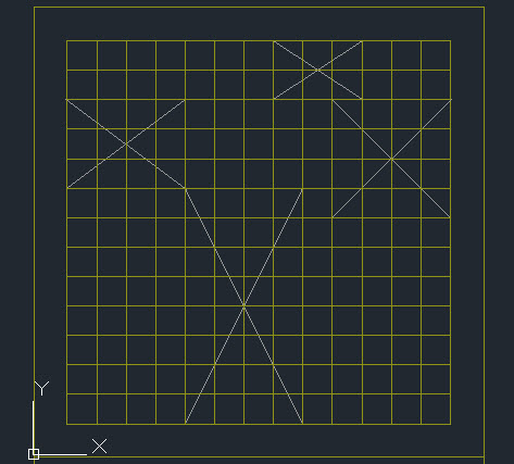
SH.1.7. Use the DIVIDE command to divide one of the edges into 13 divisions of 44 inches. If you do not see the divisions change the value of PDMODE to 3 by typing PDMODE at the command line. The various settings for PDMODE change how points appear. In the image below the points appear as X's because PDMODE was set to 3. To adjust the size of the node points type PDSIZE at the command line. The image below shows a value of 12 for PDSIZE.

SH.1.8. Complete the 44 inch grid using the COPY command. To snap to the node points, you must turn on the object snap for Node.

SH.1.9. Erase the node points after you have made your grid.
SH.1.10. This grid will be used to locate the walls of your house. The most productive way to plan out your house is to use pen or pencil on trace paper laid on top of the grid. You can print out a Grid for Planning the Small House for this purpose. Trace paper will be provided in class.
The following are required:
Living/Dining room: 4 x 7 grid squares
Kitchen: 3 x 4 grid squares
Bathroom: 2 x 3 grid squares
Bedroom: 4 x 4 grid squares
Entry and hallways to connect rooms as required.
The front door must enter into a hallway or entry vestibule.
S.H.1.11. Include the locations for doors and windows on your paper plan.
S.H.1.12. Scan and upload your plan.
Below is an example of a house plan. Develop your own design for the arrangement of rooms. Exterior space can be made into patios or open yards. IMPORTANT: This is only one possible arrangement. You are asked to generate your own arrangement of spaces.

H.Skalska_Plan For a Small House
Part 2
SH.2.1. Discuss your plan withyour instructor before completing this part. It's much easier to make revisions before you put your plan in AutoCAD.
SH.2.2. Lock the grid layer. This will keep you from accidentally moving it.

SH.2.3. Before putting the walls on your plan, you will be making a few blocks. There are different types of blocks. Some are graphic symbols. They are drawn the size they would appear on the printed sheet. When those types of blocks are inserted, they are scaled according to the scale that the drawing will be printed. Others are drawn to their full scale. A chair for example, is drawn to its full size. In this exercise, you will be drawing the second type of block like the chair that is drawn to its actual size. The blocks you will be making will reside in your current drawing file unlike the Wblocks that are made as separate files.
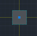
Make a block that represents a column. Set your layer to the A-FULL-WALL. Draw an 5” x 5” square that is precisely centered on a grid intersection. Fill the column with solid fill. The fill should be on the fill layer. Keep in mind that your design may not require columns. In the example plan above you will see a few columns.

SH.2.4. Make a block of your column. This time just enter B for Block. The BLOCK command is used instead of the WBLOCK command when the block will remain inside of the file. If you would like to insert the block into other files, it is best to make a Wblock. In this case the block will remain inside this file, so just use the BLOCK command.
SH.2.5. Name the block Column. For the Pick point select the grid intersection. Click on the Select Objects icon and make a window around the column. Click on Ok.
SH.2.6. If you click on the column, you will notice that the blue grip appears at the center. That is the insertion point. You can drag and place a block using the grip that appears at the insertion point.
SH.2.7. Set your layer to the Door layer. Make a door panel that is 1-3/4” x 36”. Then draw an arc to form the doors swing using the ARC command, and the Start, Center, End option and selecting point in the order shown below.


On the same layer, draw 1 -1/2” x 5” rectangles to represent the door frame.

SH.2.8. Make the door into a block called Door. Important: The grip (blue square) shows the location of the pick point.

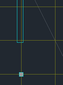
SH.2.9. Next make X's to represent the locations of rooms. The image below shows the beginnings of a layout for the arrangement of rooms. The rooms are shown with the gray X's. The X's can be used in the planning stages and erased later.
SH.2.10. Set your layer to the layer for full height walls. Wall thicknesses for exterior walls must be 8", but they should not be centered on the grid. Instead they should be 2.5" toward the inside of the house. Wall thicknesses for interior walls must be 5". Interior walls must be centered on the grid. Notice the relationship of walls to the grid below. The interior walls are centered. The exterior walls are offset.
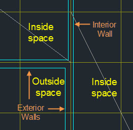
Walls must extend 2 1/2" beyond grid intersections.

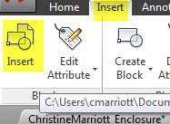
SH.2.11. If you have columns, use the Insert tool to insert the column block. If you click on the arrow next to the block name, you will see a list of all of the blocks in your file. Insert columns as needed. It is not necessary to include a column where you have walls. Place them where you have large areas of glass. If you have large expanses of glass, make sure that you have a wall or column every 4 grid modules. Once a block is inserted, you can make copies of it or you can continue to use the Insert tool.

In the image below a column has been shown in the line of an exterior wall. Notice how the column is centered on the grid, not on the exterior wall.
SH.2.12. Determine where doors will be located to connect the spaces. Insert the door blocks. Use the Rotate and Mirror tools to modify their orientation. Center doors between grid lines. Notice how the door is placed relative to the walls so that it is centered between the grid lines.

SH.2.13. Insert frames, glass and sills using the graphics shown below. You can have large lengths of glass or smaller windows. Place frames (blue rectangles) at the ends and at grid intersections. The white lines represent the glass. Place the glass on the grid lines. The gray lines represent the sill below. Include sill lines at window frames and at the edges of the floors at your doors.


SH.2.14. Fill the Cut walls with solid fill on the Fill layer. You may want to turn off the grid layer before filling the walls.

SH.2.15. Once the rooms are enclosed, erase the x’s.
SH.2.16. Go to the Block Folder and download AutoCAD blocks as needed to furnish all of the spaces in your plan. Please note that there are blocks within the folders, but they may not appear immediately (not sure why, but I am working on this). Most of the blocks are plan views. IMPORTANT: Download the blocks before inserting them. Use the Insert tool to bring the block into your file. Inserting the blocks keeps them as blocks. If you cut and paste them into your drawing their block features are eliminated.

SH.2.17. Kitchen counters are typically 25" deep. Islands and peninsulas are typically 36 inches deep. Spaces between counters should be no less than 42" but 48" is more comfortable. Draw the counters on a layer that prints lightly.
SH.18. Upload the drawing file. There is no need to print at this time.
Part 3
SH.3.1. In the same file as Parts 1 & 2, begin setting up to construct the section and elevation of your house. Below is an example of a house section (above) and elevation (below). It is highly recommended that we discuss where you will cut your section and which elevation you will draw. This may save you from having to make revisions later.

J.Jasso_Section & Elevation
SH.3.2. Create the following new layers.
Layer A-SECT-PRFL, color 4 (This layer will be for the outer profiles of walls, roofs and the top of the floor.
Layer A-ELEV-LGHT, color 8
A-ELEV-MEDM, color 6
A-ELEV-HEVY. color 5
SH.3.3. Make a copy of the 56 foot square directly below the square surrounding the plan.
SH.3.4. Establish horizontal floor lines as shown in the image below. Those lines represent the top of the floor or ground and will be erased later. The top drawing will be a section through the house. The bottom drawing will be an elevation view.

Use projection lines from the plan to construct your drawings. In the image below the plan is at the top projection lines (command Xline) are used to construct the section and elevation below.

Keep in mind the following:
Roofs should be drawn 12 inches thick. A glass roof is also shown in the image above.
Cuts through walls, roof and ground/floor should be drawn on the A-SECT-PRFL layer.
Objects that are not cut should be shown with lighter lines using the A-ELEV layers.
The graphics for windows in section are similar to the graphics for windows in plan.
Typical walls are 8'-0" high.

SH.3.4. Fill your cut objects. Use the fill layer for this. The ground/floor is cut as well. Show three feet of fill below the ground/floor line. Erase the line at the bottom of the fill after you have filled the area. Notice in the image below that there is no line where walls meet the ground or on the bottom of sides of the fill areas that represent the earth.

SH.3.5. Insert blocks into your elevation and section from the folder where you found the plan blocks. If possible, coordinate the objects with what you are showing in plan.
SH.3.6. There is no need to print to pdf at this time.
SH.3.7. Save your drawing file, close your drawing file, and upload it to your Google Drive folder.

.
.
.